10" f/4.5 NEWTONIAN COLLIMATION TEST I

02 January 2008

The purpose of this web page is to detail the procedures and results I conducted collimating a 10" aperture Newtonian reflector with a focal speed
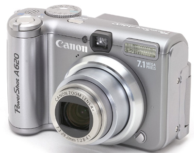
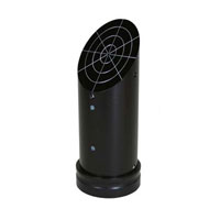
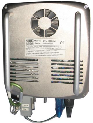
of approximately F/4.5.   The main tools I used to conduct this were a Kendrick's 2" laser collimator, STL11K CCD, and a Cannon A620 P&S digital camera.

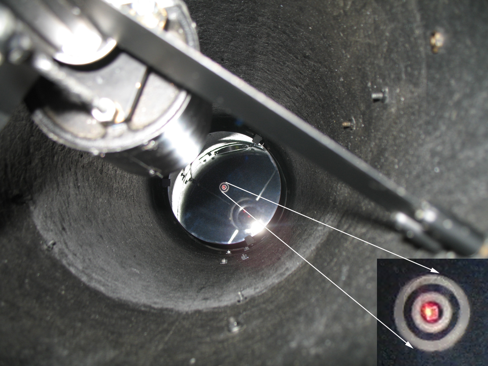
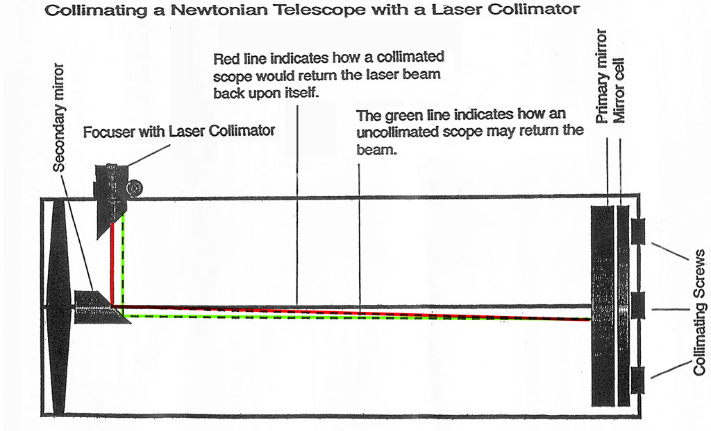
Initial collimation was done using the laser collimator by adjusting the Newtonian's secondary mirror screws to make the laser beam coincident with respect
to the center of the primary mirror (step 1).  The primary mirror screws were then adjusted to make the return beam of the laser coincident with respect to the
entrance of point of the laser collimator, by looking at the bottom of the focuser from the front of the scope (step 2); see the Kendrick's Newt. diagram below.
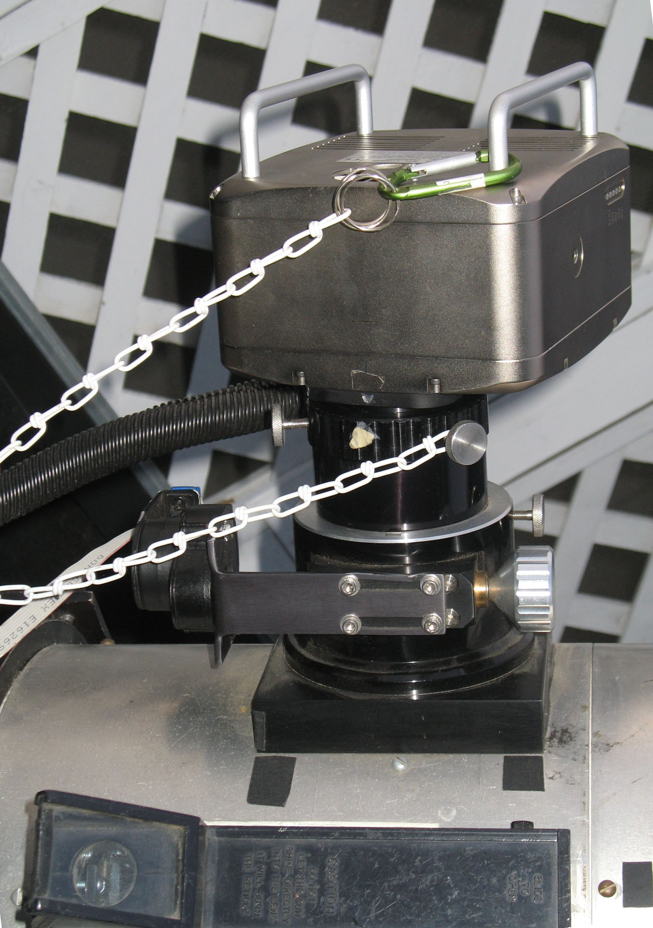
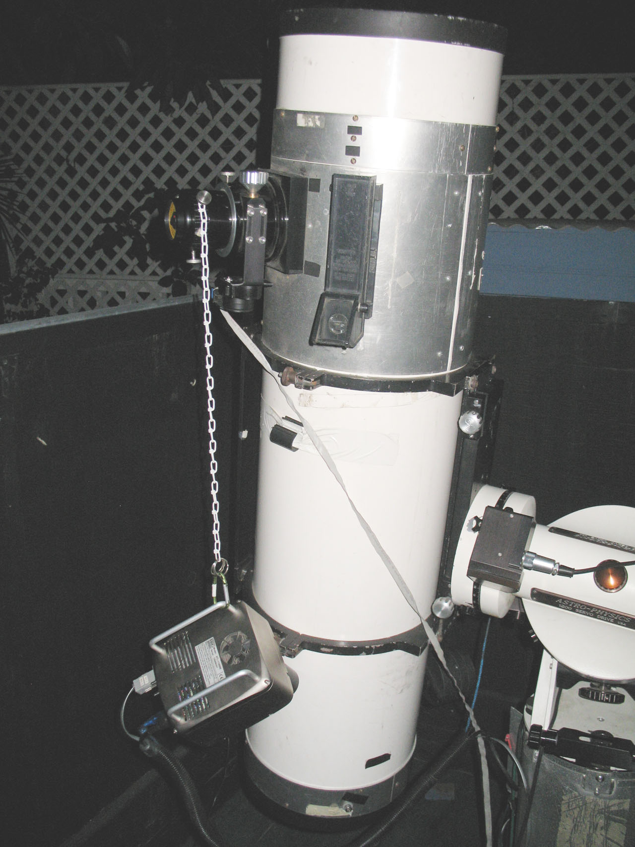
Note that all weights, including the camera itself, were used while collimating.  The CCD was hung off the side of the 2" adapter while collimating to replicate
weight load as closely as possible; see below.

Picture above left is with the camera at the "testing" position.  Picture in the middle is a close-up of the camera at the "testing" orientation.  Picture on the right
Is Newtonian being collimated with Kendrick 2" laser collimator with SBIG STL-11K CCD camera hanging-on focuser to maintain camera weight load.


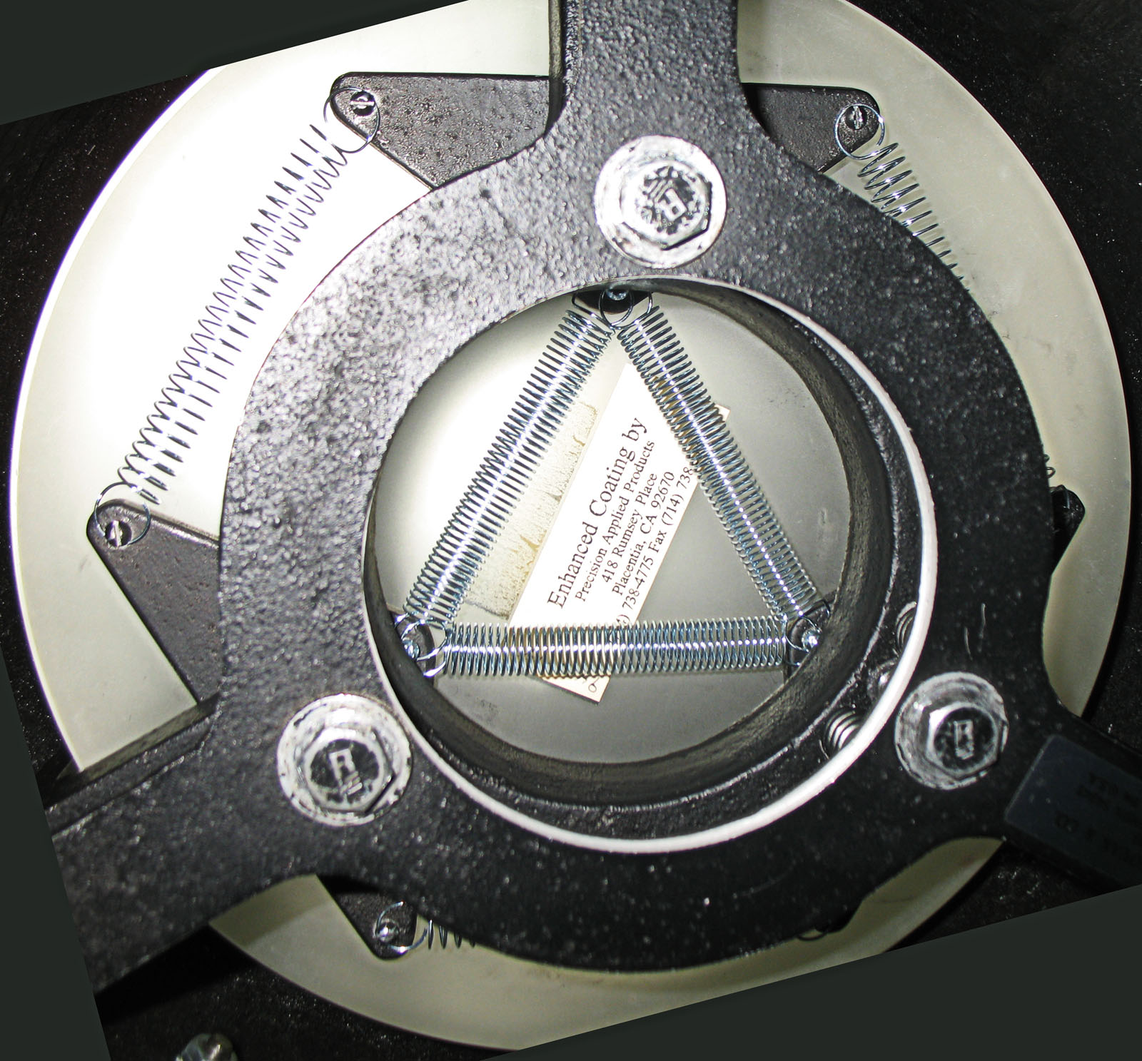
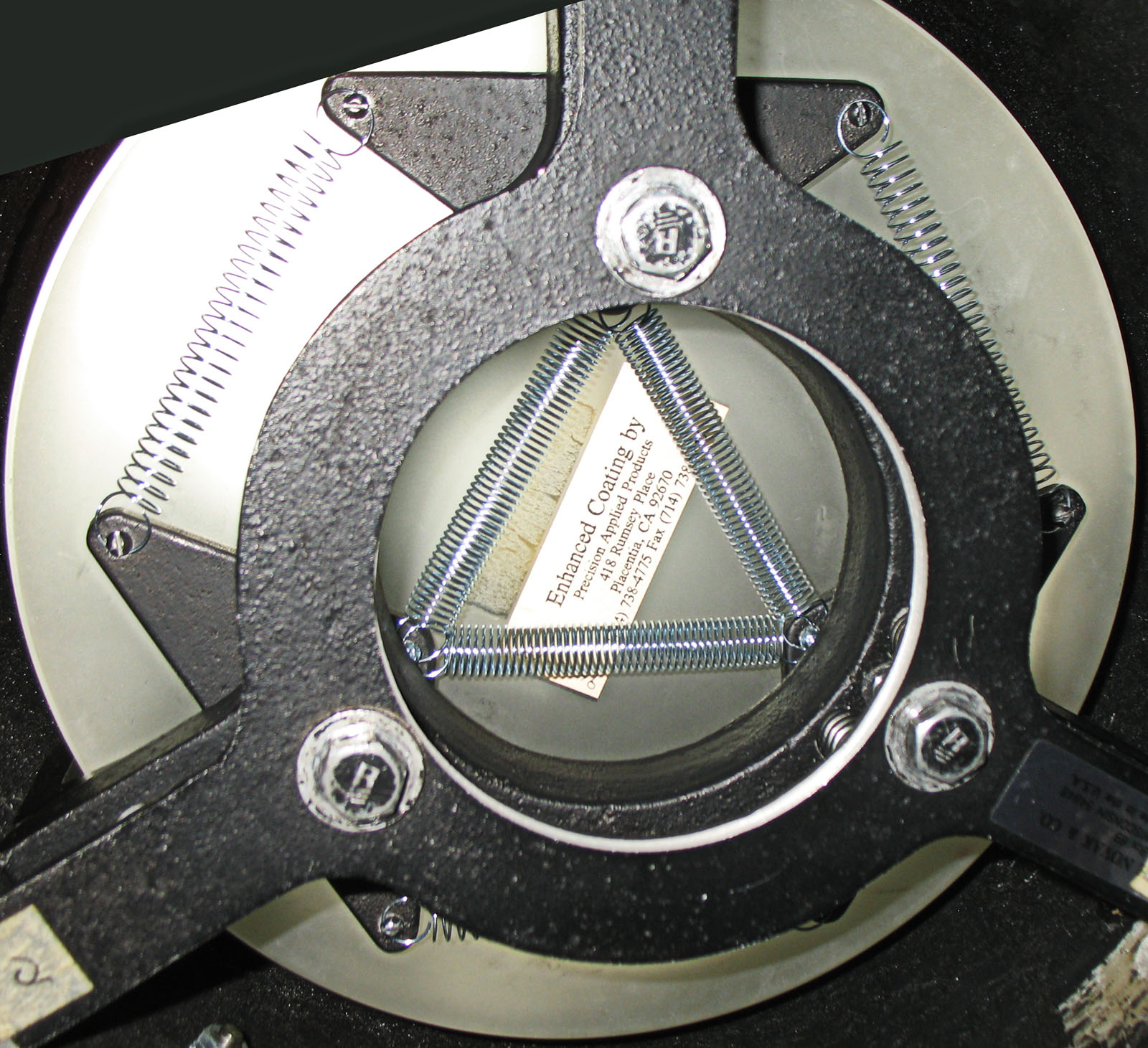
The primary mirror's support cell was reinforced with springs to assure that the triangular support pads would not change orientation or otherwise move;  see
image below.


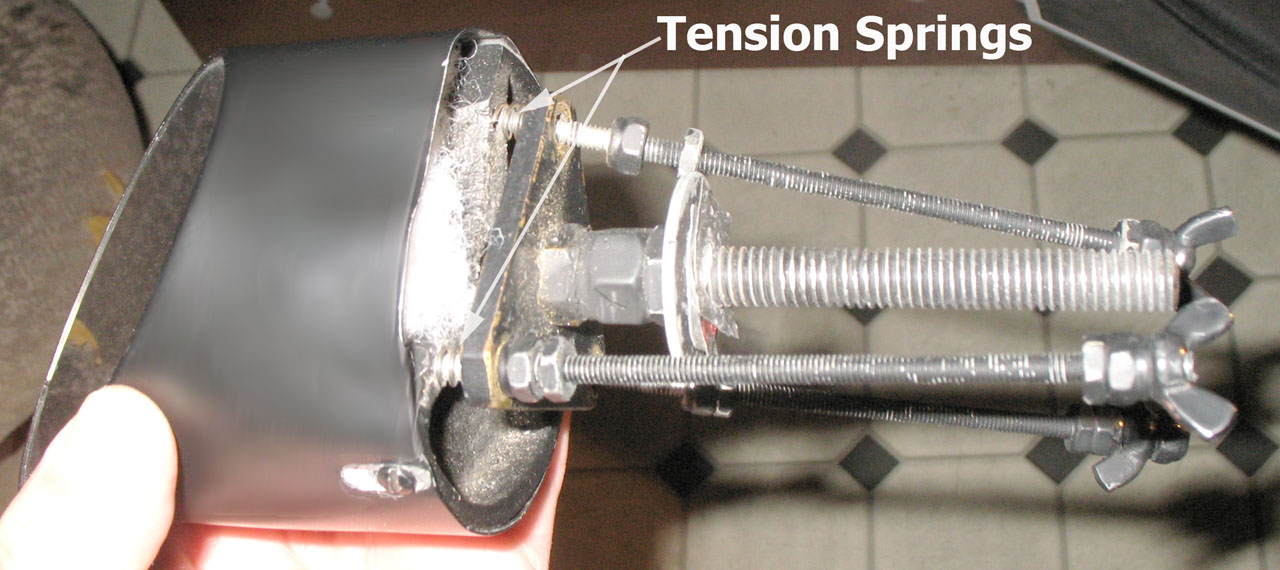
High tension springs were introduced in the secondary mirror support to limit movement after adjustment; See below

The clips holding the mirror against the mirror cell were reinforced with external lock washers.  In any case, these will have to be retightened or otherwise
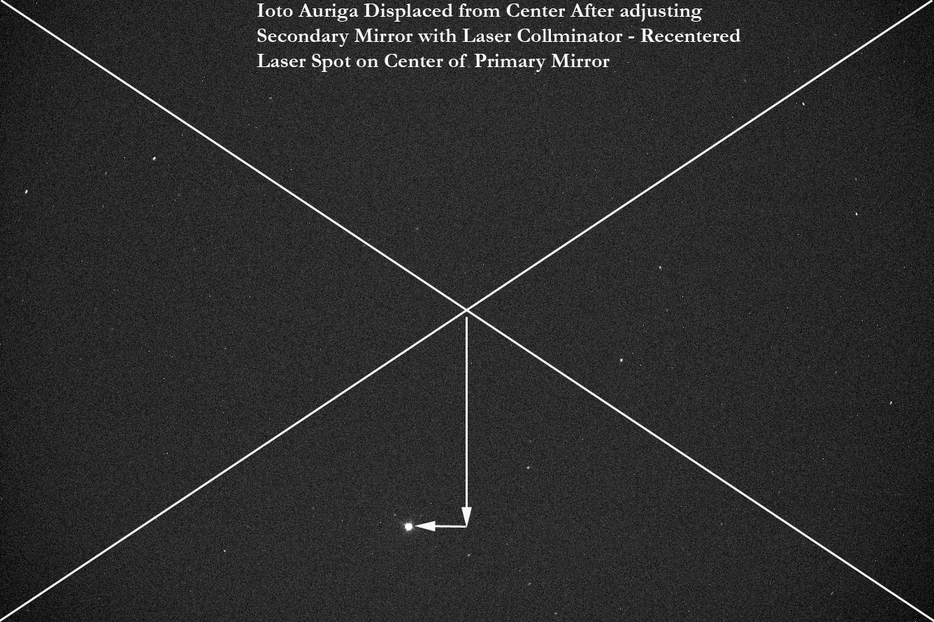
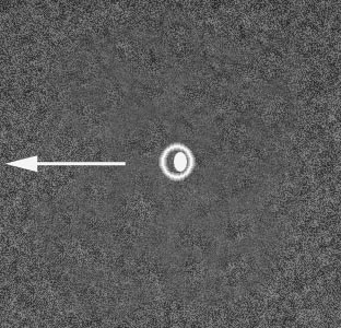
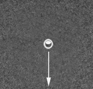
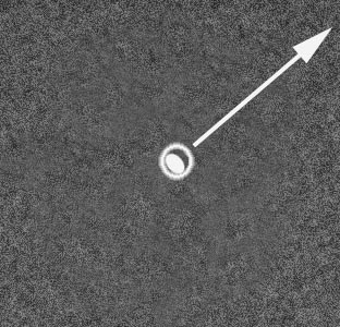
examined before imaging use. The SBIG STL-11000 CCD camera was used to collimate the primary mirror with respect to the center of the CCD's image plane;
same collimation adjustment as in "step 2" above.  Since this was the actual image/weight load configuration I was imaging with, any difference in collimation
between this and using the laser alone would manifest the "delta-Adj" of the imaging system with respect to the laser-optics system under similar weight loads.


300 Step out-of-focus image of Omicron Per.  This was made prior to any CCD directed primary mirror screw adjustment

300 Step out-of-focus image of Omicron Per.  This was done after 7 steps of CCD directed primary mirror screw adjustment

300 Step out-of-focus image of Omicron Per.  This was done after 14 steps of CCD directed primary mirror screw adjustment

NOT BAD? BETTER? NOT MUCH HAPPENING!


As the three (3) images of the out-of-focus images shown above, it was very hard to determine whether my efforts were making the optical alignment between
the primary mirror, secondary mirror, and/or the CCD image plane more exact or worse.  Omicron Per. was getting low, so I choose another star, Iota Auriga,
to continue the alignment process.  I then used a different, and more sensitive technique to analyze the collimation error.  Instead of using a star image that was
over 300 steps out-of-focus, I used a highly magnified image of a star just slightly out-of-focus.  Shown below are simulated images of the slightly out-of-
focus Iota Auriga. Because scintillation blurs the symmetry of the images, I used these to depict what was optically "going-on." Using a 1x1 binned frame about
120x120 pixels across, coincident to the center of the image plane.  I examined these out-of-focus patterns and verified that by displacing it in the opposite
direction of the "tight-beam" or parallel with minor-axis of the ellipsoid, toward the empty circle using the primary mirror adjust bolts, collimation could be
rendered accurately.  Using a schematic diagram of the primary mirror's rear adjustment bolts showing how they displace a stellar image away from the center
of the image plane, I could refine the shape and placement of the "ellipsoid" to become circular and centered-on and within the diffraction ring.


 Iota Auriga requiring a primary mirror  Iota Auriga requiring a primary mirror  Iota Auriga requiring a primary mirror
 adjustment to shift the stellar image to the  adjustment to shift the stellar image to the  adjustment to shift the stellar image to the
 left.  This would require a CW movement  bottom.  This would require a CCW  right and to the top.  This would require
 on the bottom left primary mirror bolt.  movement on the top primary mirror bolt.  a CW movement on the top bolt and a CCW
     movement on the bottom left mirror bolt.


 This is a schematic diagram of the primary mirror's rear adjustment bolts showing how a 15 degree rotation results in a star's
image shift with respect to it original placement in the center of the CCD optical plane.  Typically with a slightly out-of-focus
star, only a 5-degree or less rotation would be required to properly adjust the collimation while keeping the star inside the
120x120 pixel box.


RAW NOTES

 FINAL NOTES


Primary Mirror Cell before CCD Alignment

Primary Mirror Cell after CCD Alignment


Laser spot on primary mirror after CCD collimation alignment was complete.  Note its displacement at the 10 o'clock position.  The secondary mirror adjustment screws were adjusted to make the beam coincident with the center of this target.  This resulted in Ioto Auriga's 45' displacement from the center of the CCD image plane as shown at right.  This is almost a 45 arc minute displacement from its previous placement in the center of the F.O.V. prior to re-collimating the secondary with respect to the primary


 Despite the displacement of Iota Auiga from the center of the image plane after re-collimating the secondary mirror with respect to the primary mirror using the
Kedricks 2" laser collimator, the slightly out-of-focus image of Iota Auriga was still symmetrical.   Furthermore, on flipping the optical tube to point west and
re-collimating using the laser with secondary mirror adjustment alone, the slightly out-of-focus stellar image maintained it symmetry.  Examining the system
one day later, in the position I conducted the secondary and primary mirror adjustment (laser and CCD assisted) on objects rising in the east (90 deg. azimuth)
only laser assisted secondary mirror adjustment was required to make the laser beam coincident with the center of the primary to yield a highly symmetrical
out-of-focus pattern on slightly out-of-focus bright stars.  Another check was made after flipping the optical tube to the setting (west) position and only slight
secondary adjustment was required to make the laser beam coincident with the center of the primary.  The resulting collective 500 minute exposure  (50 
10-minute sub exposures) shows fairly acceptable stellar images considering the speed of the optical system (F/4.5) and the 2-stage coma corrector.


Back to Astroimaging Page

Please send feedback to: James R. Foster E-Mail at jrfcomet@sbcglobal.net